Many suggestions have already been made as to how losses in energy, pressure or velocity arising in the transport of liquids or gaseous media can be reduced. Thus for the purposes of inhibiting the formation of air-bubbles, which provoke an increase in the resistance to flow, a British Patent No. 409,528 for a pipe has been published, which is wound in a screw-form manner and its cross-sectional surfaces are formed by two arcs of a circle. From the British Patent No. 28,5343 of 1913 AD, the application of a pipe with an egg-shaped cross-section was made known, which was provided with flow-directing slats to inhibit the formation of vortices. In the U.S. Patent No. 1,655,197 as well as in the Schauberger - Swiss Patent No. 126637, cylindrical or conical pipes were proposed with the object of reducing friction by converting it into rotation, for which the pipe axis served as the rotational axis. Lastly, the Schauberger - Austrian Patent No. 28099 depicts the use of indented and twisted pipes.
This invention (see fig. 17) relates to a conduit or pipe for liquid or gaseous media, which is intended to prevent encrustation and to reduce flow losses, wherein the pipe cross-section is formed of several curved arcs of a circle and the pipe is coiled in a screw-form manner. The invention also consists in the fact that the cross-section is egg-shaped with an indentation on one side adjacent to the pointed end of the egg and that the pipe is first twisted upon itself before the whole is formed into a coil. With the aid of such a pipe, the conveying capacity and efficiency is improved due the reduction of frictional losses and the prevention of encrustation. In order to increase the conveying capacity, the coiling of the pipe around an imaginary cylinder has proved to be particularly effective. For the same reason, the pipe can be rotated in a normal manner, whereby the central axis of the coiled pipe arrangement is also the axis of rotation. It is also advantageous to narrow the cross-section of the twisted pipe.
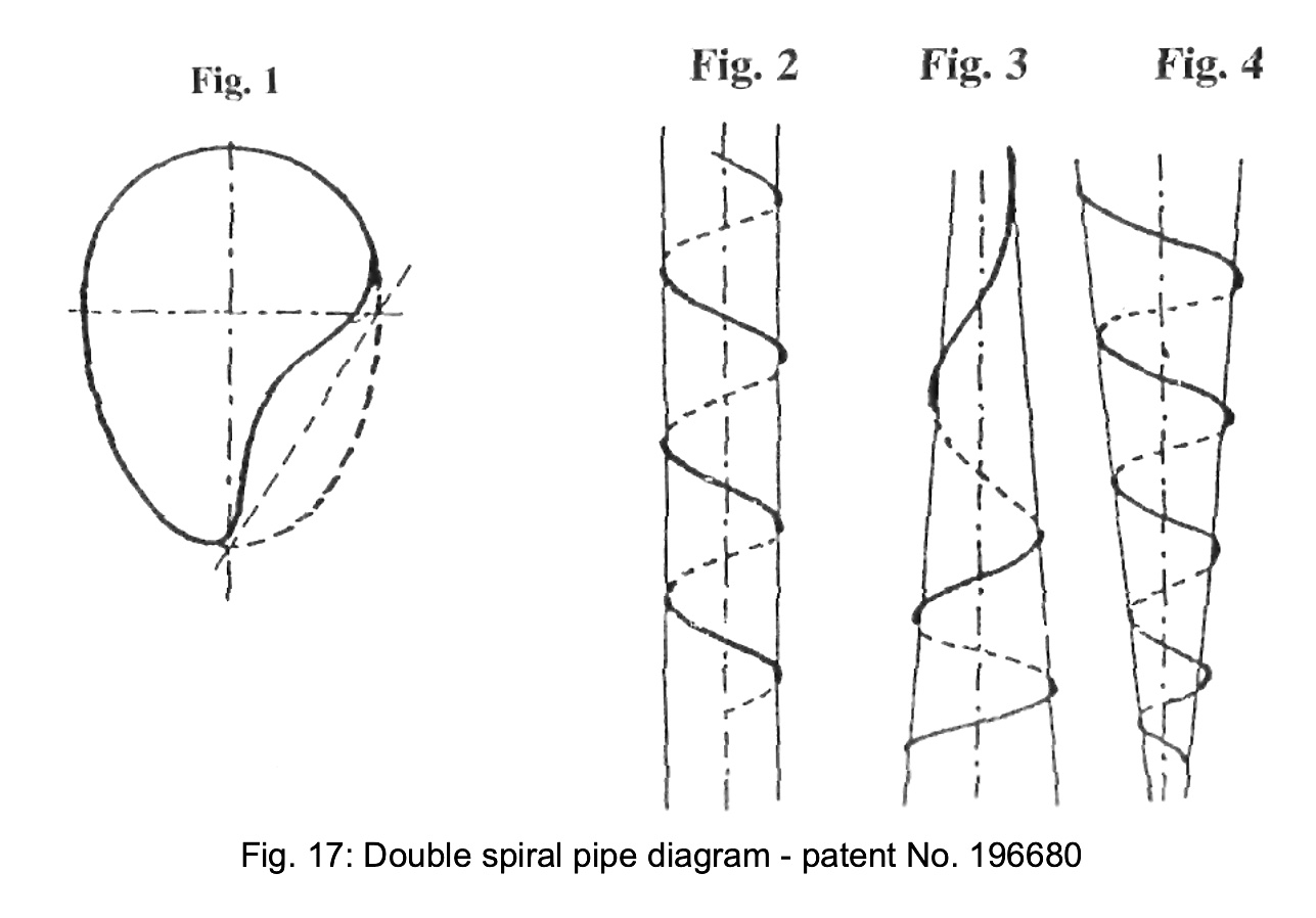
In the attached drawing the cross-sectional form and the coiling of the pipe are depicted schematically. Figure 1 shows the cross-section of the pipe and Figures 2-4 the pipe in its coiled configuration.
In Figure 1 the cross-section of the pipe in question is shown with a curved indentation on one side adjacent to the smaller end of the egg-shape. The coiling of the pipe can be effected by winding it round an imaginary cylinder,
106
Figure 2, or around an imaginary cone, Figures 3 & 4, prior to which the pipe is first twisted about itself. If the pipe is wound around an imaginary, circular cone corresponding to Figures 3 & 4, then pipe cross-section can be narrowed either towards the point or towards the base of the cone. Furthermore, for purposes of reducing frictional losses and the avoidance of encrustation, the whole arrangement can be rotated by suitable means, wherein the central axis of the coiled arrangement is also the axis of rotation.
Patent Claims
1. The invention of a pipe for liquid and gaseous media for the prevention of encrustation and the reduction of flow losses, whereby the pipe cross-section consists of several arcs of a circle and the pipe is wound in a screw-form shape, is characterised by the fact that the cross-section of the pipe is egg-shaped with a curved indentation on one side adjacent to the pointed end, and that before being coiled, the pipe itself is first twisted.
2. In accordance with Claim 1, the pipe is characterised by being wound around an imaginary cone.
3. In accordance with Claims 1 & 2, the pipe is characterised by the fact that the coiled arrangement as a whole can be rotated about the central axis of the same.
4. In accordance with Claims 1 to 3, the invention is characterised by the fact that the pipe cross-section narrows in one direction.