
A Tesla coil is an electrical resonant transformer circuit invented by Nikola Tesla around 1891. It is used to produce high-voltage, low-current, high frequency alternating-current electricity.
Tesla coils can produce higher voltages than other artificial sources of high-voltage discharges, electrostatic machines. Tesla experimented with a number of different configurations consisting of two, or sometimes three, coupled resonant electric circuits.
Tesla used these coils to conduct innovative experiments in electrical lighting, phosphorescence, x-ray generation, high frequency alternating current phenomena, electrotherapy, and the transmission of electrical energy without wires. Tesla coil circuits were used commercially in sparkgap radio transmitters for wireless telegraphy until the 1920s, and in pseudomedical equipment such as electrotherapy and violet ray devices. Today their main use is for entertainment and educational displays. Wikipedia, Tesla Coil
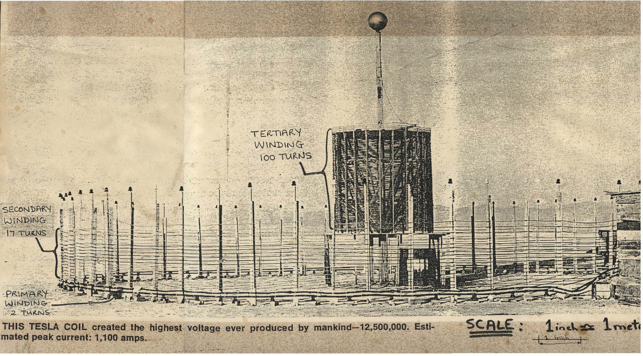
"12 Million volts." Article about Robert Golka's work in Wendover, Utah, replicating and modernizing Tesla's generator. Called "Project Tesla." Secondary coil has resonance of 50 kHz. An additional coil resonates at the second harmonic, 100 kHz. (Radio Electronics. 47, June 1976.)
"Scientific aspects of intense magnetic fields & high voltages." (Nature (London). 120(3031), Dec. 3, 1927. p. 809-811.)
"Tesla coil & Geissler tube hook-ups." Brief notes with diagrams of Nikola Tesla coil and Geissler tube. (Electrical Experimenter. July, 1919. p. 240, 242.)
"Nikola Tesla and Oudin coil data." Refers to Electrical Experimenter. May 1917. (Electrical Experimenter. July 1919. p. 240, 242.)
THE TESLA COIL (long post but important)
Patent No. 462,418 — “Method of and Apparatus for Electrical Conversion and Distribution”
Filed: February 4, 1891
Issued: November 3, 1891
By 1891, Nikola Tesla had already revolutionized alternating current (AC) systems with his polyphase motor patents. But here, he moved far beyond AC power transmission into a new physical regime — high-frequency, high-potential oscillations that could transform energy without moving parts.
This patent, issued before the invention of radio or the discovery of the electron, established the core operating principle of what later became known as the Tesla coil: The controlled discharge of stored electric energy through an air-gap into an inductive circuit to produce rapid electrical oscillations of extremely small period.
Tesla’s design replaced mechanical commutators (which limited frequency) with a spark-gap interrupter, allowing electrical oscillations reaching millions per second — a realm impossible for rotating machines.
This invention became the foundation of all wireless and high-frequency technologies: radio, fluorescent lighting, X-rays, and Tesla’s later Earth-resonant wireless power system.
In his 1916 interview with his attorneys (pre-hearing testimony defending his radio patents), Tesla proudly declared:
“This type of apparatus is identified with my name as certain as the law of gravitation is with that of Newton… The greatest men of science have told me that this was my best achievement.”
Tesla was defending not merely a laboratory device, but the principle itself — the oscillatory condenser discharge — which others later adapted for radio and arc transmission.
When rivals like Poulsen, Marconi, or Thomson made variations of his design (adding hydrogen, rotary gaps, or rectifiers), Tesla pointed to his 1891 patent diagram and said, in essence:
“They’re just tinkering with my engine.”
Every example he cited (Poulsen arc, Marconi’s twin wheels, Cooper Hewitt’s rectifier) modifies positions in his 1891 schematic:
• D = Spark gap or “break.”
• L L = Self-inductive lines (coils).
• B = Conducting leads from the generator.
Each rival merely replaced one of these positions with a variant component — but none changed the governing principle.
Hence Tesla’s frustration:
“Not a vestige of invention… they have only done what a 30-year-old mule is capable of.”
Tesla’s patent is built on three experimentally verified phenomena:
1. A charged condenser (capacitor) can discharge through a circuit in an oscillatory manner — energy surges back and forth between the electric field of the condenser and the magnetic field of the coil.
2. If a current rises and falls rapidly in a conductor, connecting a condenser to two points on that conductor modifies the current — the condenser adds a controllable time-delay or “elasticity” to the current’s flow.
3. The behavior depends on four parameters: capacity, self-induction, resistance, and rate of energy supply/decay — or in modern terms, C, L, R, and Δt.
From these, Tesla designed a method of electrical conversion — taking electrical energy in one form and converting it to another (different voltage/current ratio) by oscillatory discharge, without moving parts.
Tesla describes the generating circuit and working circuit as two coupled systems (Figure 1):
• A = High-tension generator (AC or DC).
• B B = Conductors from the generator.
• F = Condenser (capacitor) connected to the generating circuit.
• D = “Break” — a spark-gap (air-space where disruptive discharge occurs).
• C = Working circuit (the load side), which may include lamps or motors (G).
Step-by-step operation:
1. The generator charges the condenser F until the voltage exceeds the dielectric strength of the air-gap D.
2. Breakdown occurs at D — the air becomes conductive, and the condenser discharges abruptly through the working circuit C.
3. This disruptive discharge sets up oscillations — energy bouncing between the condenser’s electric field and the inductive field of the circuit.
4. The current decays, the gap de-ionizes, and the condenser begins charging again from the generator.
5. The process repeats automatically, forming a succession of discharges.
The result is an alternating current of extremely high frequency, “many millions per second,” created without mechanical means — a purely electrical oscillator.
Tesla notes that the more nearly the rate of supply equals the circuit’s ability to charge and discharge, the more rapid and efficient the operation becomes.
---
For me information like this, follow Facebook page Dr. Nikola Tesla
--
In Figure 2, Tesla refines the system by adding a secondary condenser E across part of the working circuit L. When a discharge occurs at D:
• The surge divides — one path through E, one through L.
• The inductive part L resists the sudden change in current (back-EMF).
• The condenser E instantly accepts charge (“time is gained”) and then discharges through L, smoothing and shaping the oscillation.
This design allows control over the current waveform and increases overall efficiency. Tesla states that the faster the discharges succeed one another, the smaller the required capacity, and the greater the efficiency — because dielectric loss and heating diminish at ultra-high frequencies. He confirms these claims with experiments (“This is confirmed by practical results.”).
Tesla defines the process as: “Converting discharges of high tension and small volume into currents of lower tension and greater volume.”
In modern terms, the oscillatory system behaves like a frequency converter and impedance transformer, able to deliver:
• High current / low voltage for loads like motors, or
• High voltage / low current for dielectric experiments or transmission.
It is the foundation of his later resonant transformer and wireless transmitter designs.
Tesla’s “conversion” does not refer merely to voltage transformation but to dynamic transformation through controlled resonance — a conversion of waveform, frequency, and intensity via oscillatory action.
Tesla explicitly enumerates three major advantages of his disruptive discharge system:
1. Reduced Condenser Size – Higher repetition rates mean smaller capacitors can deliver the same energy output.
2. Increased Efficiency – Rapid oscillations reduce dielectric heating losses.
3. Enlarged Conversion Range – The system can accommodate broader voltage/current transformations than ordinary transformers.
He calls this system “radically different” from anything that came before — not only in the number of oscillations but in the manner in which they are obtained.
Tesla’s two claims capture the entire essence:
1. The method of electrical conversion herein described, which consists in charging a condenser or conductor possessing capacity and maintaining a succession of intermittent or oscillating disruptive discharges of said conductor into the working circuit containing translating devices.
2. In a system of electrical conversion, the combination of a generator, a generating circuit possessing capacity, and a working circuit operatively connected through one or more air-gaps, the electrical conditions being so adjusted that an intermittent or oscillating disruptive discharge from the generating into the working circuit will be maintained.
In short: store charge → discharge disruptively → maintain oscillations. That is the birth of the electrical oscillator — the fundamental part of every Tesla coil, radio transmitter, and resonant transformer ever built.
The “break D” is the heart of the machine. Tesla calls D the “break”, later the “disruptive discharge gap.” It performs what no mechanical switch could:
• Acts as an automatic valve, conducting only when the potential reaches breakdown.
• Interrupts conduction the instant the stored energy is exhausted.
• Resets the system for the next charge.
This non-mechanical “switch” allowed Tesla to generate self-sustaining oscillations purely through electrostatic tension and inductive reaction — what he later described as “a living breathing system of electrical vibration.”
At the end of the patent, Tesla adds a subtle but profound line:
“The ground may be conveniently used in lieu of the return wire.”
At the time, this was just an engineering simplification — a way to avoid long copper loops. But later, this insight became the cornerstone of his wireless power system: the Earth itself as part of the circuit — a global conductor in electrical resonance.
By 1916, Tesla had watched his apparatus rebranded in hundreds of forms:
• Valdemar Poulsen filled the gap (D) with hydrogen for steadier arcs . Tesla: “He employs all my instrumentalities, but calls it a new wireless system.”
• Karl Ferdinand Braun/Guglielmo Marconi inserted an extra gap between self-inductive lines (L L). Tesla: “He Marconi gets a Nobel prize for doing it.”
• Peter Cooper Hewitt added a mercury-arc rectifier in conductor (B). Tesla: “Has nothing to do with the performance.”
• Marconi used two rotating wheels instead of one. Tesla: “The Lord himself could not make anything else happen.”
Each so-called improvement merely substituted or duplicated an element already shown in Tesla’s 1891 diagram. What they called innovation, Tesla saw as mechanical tinkering, not creative insight. Hence his bitter but justified remark:
“Invention has been degraded, debased, prostituted… Not a vestige of invention.”
Tesla never used the name Tesla coil himself — he referred to it as an oscillatory transformer or disruptive discharge apparatus. But the world eventually attached his name to it because:
• The oscillatory condenser discharge principle defined in this patent became the central feature of every Tesla coil system (primary capacitor + spark gap + coil).
• When a secondary resonant coil was added (as in his later work, 1893–1897), it turned into the classic Tesla coil known today — a resonant energy transformer operating by the very law described here.
So, Patent 462,418 is the intellectual birth certificate of the Tesla coil — not as a single device, but as an entire class of apparatuses built on the same electrostatic oscillation principle.
Tesla’s 1891 invention marked a shift in electrical engineering — from steady currents and mechanical rotation to oscillatory, resonant systems governed by frequency, capacity, and inductance.
It introduced:
• Electrical resonance as a tool.
• The replacement of mechanical timing with natural oscillation.
• The first explicit use of electrostatic charge storage and disruptive discharge as a regenerative engine.
When Tesla said in 1916 that this was “universally employed everywhere,” he was right — radio transmitters, fluorescent lamps, induction heating, radar, and even modern switch-mode power supplies all trace lineage to this principle.
In 1916, he summarized the matter with quiet fury and pride:
“If these men knew what I do, they would not touch my arrangements; they would leave my apparatus as it is.”
He wasn’t being arrogant — he was stating an engineering fact. The relationships among capacity, self-induction, resistance, and period that he described in 1891 remain fundamental to all tuned electrical circuits today.
The Tesla Coil — in its original, patent-defined sense — is not merely a spark generator or transformer. It is:
A self-acting electrical oscillator based on the disruptive discharge of a condenser through an inductive circuit — producing rapid electrical vibrations capable of transforming energy across circuits, with the Earth itself as the ultimate conductor.
That’s why Tesla called it his best achievement — because it was the seed of all future wireless art.
Primary Sources:
1. Nikola Tesla, U.S. Patent No. 462,418 — “Method of and Apparatus for Electrical Conversion and Distribution” (1891).
2. Tesla’s pre-hearing interview with his legal counsel in 1916, defending his radio patents from Guglielmo Marconi. Published in Nikola Tesla On His Works With Alternating Currents and Their Application to Wireless Telegraphy, and Transmission of Power (Twenty First Century Books, Breckenridge, Colorado, 2002).
See Also
Bearden on Tesla and EM Source Charge
Coil
Electric Current
Figure 16.04.05 and Figure 16.04.06 - Nikola Tesla and Lord Kelvin
Figure 16.06 - Russells Genero-Radiative Coils - Electricity Expands and Contracts
Figure 8.3 - Coiled Spring showing Longitudinal Wave
Flyback Transformer
Inductor
Magnetic Field
Magneto
Nikola Tesla
Stubblefield Coil
Tesla - Electricity from Space
Tesla messages
Tesla shield
Transformer
14.35 - Teslas 3 6 and 9
16.04 - Nikola Tesla describing what electricity is
16.17 - Negative Electricity - Tesla