The end and design of the invention is an engine wherein the actuating power is produced by a vacuum in connection with water pressure. (see Picture Gallery for the following drawings)
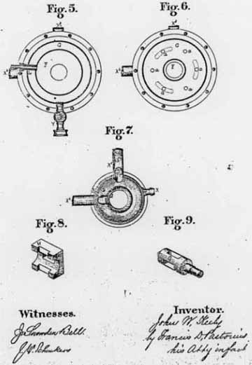
Figure 1: is a side elevation. Figure 2: is an end elevation. Figure 3: is a plan view. Figure 4: is a sectional side elevation. Figure 5: is a section through the dotted line 1-1. fig. 4. Figure 6: is a section through the dotted line 2-2, fig. 4. Figure 7: is a section through the dotted line 3-3, fig. 4. Figure 8: is a section of the valve chest. Figure 9: is the valve or plug.
Click to view Photo Gallery of this Motor
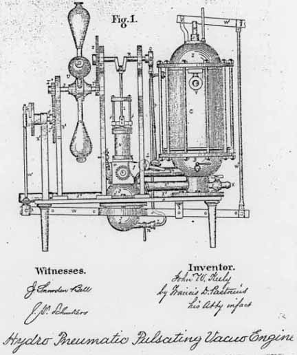
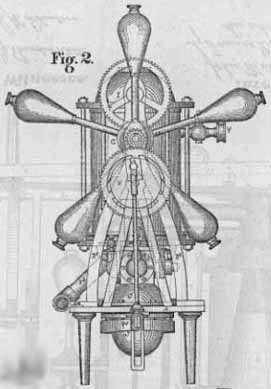
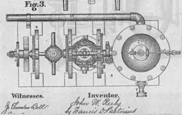
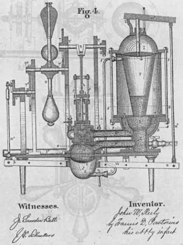
A. Figures 1, 2, 3, 4, is the bed of the engine B. figures 1, 4, is a cylindrical semi-globular vessel which is bolted to it and near its end. C is a vacuum chamber [?] chamber B. it communicates with it by means of a circle of openings, a, arranged in its base.
Within the chamber B and of very near by the same conformation as the chamber D. its waist or cylindrical part, E, fits snugly and tightly the waist or cylindrical part of the vessel B. there is a space b. between the semi-globular parts of the two vessels.
F is an inverted conical pulsating chamber placed centrally in the vacuum chamber C. its bottom opens into the vessel D. its top is closed by a pulsating diaphragm G. the stem H of which passes through a guide or box C. of the air chamber, I, which is formed from the vacuum chamber C. by the said pulsating diaphragm.
J is a water and air vessel which is suspended in an opening in the bed A of the engine, it is divided into two parts by the pulsating diaphragm K the upper part G is for water, and the lower part, d, for air, a pipe I communicates with the chamber F.
M is the valve chest and N, the cylinder of the engine, on the chamber J the valve O is of the three way plug order and is operated by means of gear wheel and toothed sector e-f figure 1. which are actuated by the eccentric rod and eccentric P, G.
R. is a crank shaft which turns in suitable bearings in the housings R. it connects with the piston and piston rod g. by means of the connecting rod h and the cross head i sliding on the guide rods j. on the inner end of the shaft R. is the eccentric Q. which actuates the gear and sector e-f. by means of the ball and socket eccentric rod P. SS are shafts which are parallel and turn coincidentally and at the same speed with the shaft R. by means of the spur and pinion gearing T', T', T2, T3 they turn in bearings of the housings R2, R3 the former carries the ball or fly wheel v while the latter has the crank wheel V on its other end.
W is a balance or compensating lever which turns on the fulcrum K. depending from the bed plate A of the engine, the ball and socket rod W1 connects one end of it to the crank wheel v while W3 connects its other end to the lever W2 which turns on a fulcrum b of the air chamber I.
To start the engine reference being had to figures 1, 4, the piston g. being on its up stroke, the cock m. of the supply pipe X is opened and sufficient water is admitted to fill the waist B of the vessel D the pipe X1 and the chamber J. above the pulsating diaphragm K. to the dotted line 4-4. the air displaced by the water is forced into the pulsating cone F and compressed in the upper part of the chamber J above the said line 4-4. an air pump is now applied to the nozzle Y of the vacuum chamber C. and the air exhausted therefrom, the chamber C. communicating with the semi-globular part of the vessel B through the circle of openings, a, in its base, and with the horizontal pipe X2 which leads from the valve chest M to the vessel B, the air is exhausted from all at the same time.
If the inlet cock, M. of the supply pipe X be opened to its extent and a full water pressure be admitted to the waist E of the vessel D it will rise in the semi-globular part of the same and also run through the pipe X1 into the upper part of the chamber J until the compression of the air in the conical pulsating chamber F and in the part, d, of the chamber J equals the pressure of the water, the cock m. of the pipe T being open to permit a free circulation of air between the chambers, the pulsating diaphragms G and K. will be extended, the stem H partaking of the outwardly motion of its diaphragm will be raised vertically and thereby lift the lever W3 it will be readily seen that there is an uninterrupted water or other fluid flow between the vessel D and the upper part of the chamber J. and an uninterrupted air flow between the lower part of the same and the conical pulsating chamber F which opens into the upper part of the said vessel D.
A weight sufficient for obtaining the requisite pressure being hung so the lever W3 its force on the stem H causes the pulsating diaphragm G to compress the air in both chambers F, J. downwardly upon the water of the vessel D. and upwardly by the diaphragm K. against the water on the pat[?] c1 of the chamber J.
The descending vibration of the lever W3 through its end or connecting rod W2 depressed the end, O, of the compensating lever W. and of consequence raises its opposite end p, the connecting rod W1 of that end turns the crank wheel V. since the shafts SSR turn coincidently and at the same speed through the medium of the spur gear and pinion T3, T2, T, T. the eccentric Q. and rod P working the spur gear and sector e-f. slowly turn the plug valve O. until its port q and the valve chest port v leading from the chamber J form a continuous port to the cylinder N.
The water in the pipe X1 in the vessel D and in the upper part of the chamber J and also the compressed air above the line 4-4 acting under the influence of the compressed air in the conical chamber F and in the lower part of the chamber J. rushes through the port, v, and pressing against the under side of the piston g, causes it to ascend; when it arrives at the end of its stroke, the eccentric Q and the rod P. together with the gear and sector e-f will have turned the plug valve V, so as to shut off all communications of this cylinder N with chamber J. and opened its port into the pipe X2 through the port X?.
The vessel B, the chamber C and the pipe X2 from one continuous vacuum, the instant the ports between the cylinder N and the pipe X2 are opened, the air and water contained in the cylinder is sucked into the vacuum, the pressure of the atmosphere acting on the piston through the openings, S, in the cylinder head makes the return or down stroke, the back pressure of the air and water being renewed by the vacuum.
The set of the crank wheel v should be such that as the piston ascends the end p of the compensating lever W should descend and the end, o ascends, whereby the lever W is raised gradually and the pulsating diaphragm G is permitted to expand or left unloaded by the expansion of the air in the chambers F, J and the pressure of the water flowing through the supply pipe X.
A few revolutions of the engine will effectually exhaust all the air from the upper part of the chamber J, the valve and valve chest ports, and from the cylinder beneath the piston.
To draw off the water as exhausted from the cylinder after performing its work as a mechanical agent, an exhaust pipe X3 taps the semi-globular part of the vessel B near its top as shown at figures 1, 2, 3, 4, 7, its other end dips into water to prevent the entrance of air, it is freed of its air at the same time with the vacuum chamber C. and the vessel B.
The pipe X3 prevents the water from raising in the chamber or vessel C higher than the bottom of the vacuum chamber C. it should maintain the same level in the vessel D. if it should rise into the pulsating chamber E. as shown at figure 4. it would reduce the volume of air and thereby materially interfere with the capacity of the engine.
When it is desired to stop the engine an air cock L on the swell or enlargement of the pipe X2 is opened which admits air to the chamber C. and destroys its vacuum.
I claim as my invention:
First: The cylindrical semi-globular chamber B. in combination with the vacuum chamber C. and the pipes X2, X3 for the purpose shown and described.
Second: The cylindrical semi-globular chamber or vessel D in combination with the conical chamber E. the pulsating diaphragm G. the stem H the lever W3, and the supply pipe X for the purposes shown and described.
Third: The cylindrical semi-globular vessel D in combination with the pulsating chamber E the pipe X1 the pulsating chamber J. and the pipe I. for the purpose shown and described.
Fourth: The chamber J. in combination with the pulsating diaphragm K. for the purpose shown and described.
Fifth: The pulsating chamber J. in combination with the valve chest M. and the cylinder N for the purpose shown and described. Sixth: The valve chest M. in combination with the pipe X2, the vessel B. and the vacuum chamber C. for the purpose shown and described.
Seventh: The valve chest M. in combination with the valve plug O. the spur gear, e. the sector f. eccentric rod P. the eccentric G. for the purpose shown and described.
Eight: The shaft R. in combination with the eccentric Q. the eccentric rod P. the toothed sector f. the spur gear e. and the valve O. for the purpose shown and described.
Ninth: The horizontal shafts R. SS. the spur gear and pinions, T, T, T2, T3 and the balance or ball wheel U for the purpose shown and described.
Tenth: The crank wheel V in combination with the rod W1 the compensating lever W2 for the purpose shown and described.
Eleventh: The air cock Z in combination with the pipe X2 for the purpose shown and described.
In testimony whereof I hereonto sign my name in presence of two subscribing witnesses.
John W. Keely, the above name petitioner being duly sworn deposes and says that he verily believes himself to be the original and first inventor of the new and useful Hydro Vacuo Engine described and claimed in the foregoing specification that he does not know and does not believe that the same was ever before known or used, and that he is a citizen of the United States.
See Also
Browns Gas Cavitation Chronology Ether Etheric Vapor Figure 13.00 - Keelys Provisional Engine showing oil splatter from rotation Figure 15.02 - Keelys Hydro-Pneumatic-Pulsating-Vacuo Engine operated with etheric vapor Figure 19.05 - Globe Motor with Provisional Engine Hydrogen HHO Implosion Keely Motor Keely Motor Company Keelys Accomplishments Keelys Mechanical Inventions and Instruments Keelys Motor Keelys Motor in Boston Keelys Patents Motor Keely Gets Angry Motor Men Disgusted Mrs. Moore on the Keely Motor Part 18 - Mind as an Engineerable Force 3.23 - Hydrodynamic Equations - Vortex Motions 7B.11 - Hydrogen 15.25 - Hydrogen and Oxygen do not exist
